
Description
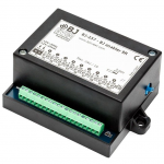
This enabler with nine relay switched contacts is designed to control up to 9 functions of the same element or of different elements: lifts, ceiling hoists, elements in a sensory room, etc.
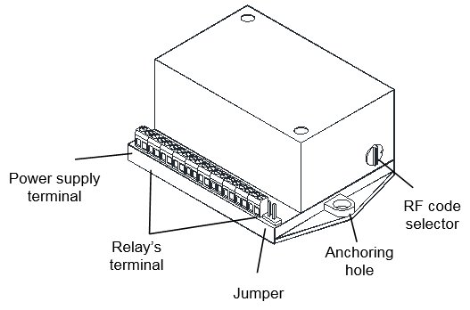
Fig. 1. BJ Enabler 9R.
You can activate the enabler remotely using any of the BJ System’s remote controllers.
Device assembly
Pre-installation
For correct installation, the enabler must be fitted in a sealed box that provides sufficient space, absence of dust and humidity and isolation from direct contact with people.
The dimensions of the box where it is installed must be at least: 120mm x 100mm x 48mm (length, width, height). It can be fitted on the surface or recessed. The enabler has two “anchoring holes” for fitting (Fig. 1). The distance between the anchoring holes is 105mm and the holes’ diameter is 4mm.
To install the enabler you must carry the enabler’s power cable and load cable’s to the box where it will be installed.
Installation
CAUTION! Electrical installation may only be carried out by a qualified electrician!
Do not make any unauthorized alterations or modifications to the unit.
The relay contact is only suitable for low voltage power supply (24 V dc/ac – 1A)
Observe the manufacturer’s instructions for the device to be operated.
For a proper installation of the device see figure 2:
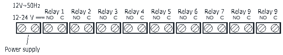
Fig. 2: Circuit diagram of the Enabler connections.
IMPORTANT!: See the device technical data to check the type and maximum loads that can be connected to the enabler.
Power cables must be stripped a distance of 5mm.
Once the enabler’s connections are made and before connecting the device to the power supply, you must choose the position on the “RF code selector” (see figure 1).
Operating modes
This enabler is designed for switching low powered devices in two selectable operating modes: in Dead Man’s mode relays are triggered as long as the transmitter button is pressed, and in pulse mode, relay is triggered and works for 1 second when pressing the transmitter button.
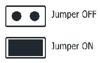
The operating modes can be configured by means of a jumper.
- Jumper OFF: dead man mode.
- Jumper ON: 1 second pulse mode
The RF selector allows up to 4 positions; each one corresponds to a RF code assigned to the enabler:

Table 1.
- S=Selector
- R1= Relay 1
- R2= Relay 2
- R3= Relay 3
- R4= Relay 4 and so on.
IMPORTANT!: change the code in the selector or the operating mode, disconnect the enabler from the power supply, wait five seconds and reconnect the circuit.