- Products
- >
- Access
- >
- USB Switch interface 2
Safety warning
In order to ensure the safe operation of the device it is recommended to read this user manual completely before starting to use the device.
Technical specifications
- Switch Inputs for 3.5 mm female jack
- USB connection 2.0
- Operating voltage and current: 5V dc, 200mA
- Size: 50 x 25 x13 mm
- USB extension cable 20 cm length included
Description
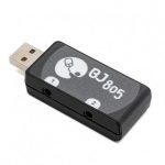
This switch adapter allows connecting up to two switches to a computer USB port and use them with different specific applications that offer scanning access.
The computer recognizes the device as a joystick and with the software provided it is possible to convert the inputs into mouse or keyboard signals depending on the user’s needs.
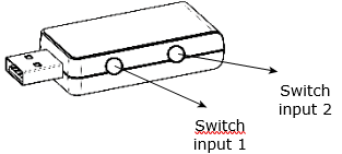
Fig. 1. USB Switch adapter.
Startup
STEP 1.
Connect the switches to the device.
STEP 2.
Connect the device to selected USB port of your PC.
STEP 3.
Set up the application that you want to control with the device.
Software configuration
Software BJ-805
BJ-805 Software allows assigning keyboard and mouse actions to the switches connected to the USB Switch adapter BJ-805.
STEP 1.
Download the installer from: BJ-805 software (available to Microsoft Windows).
STEP 2.
Once you have downloaded the file you should execute BJ-805_Setup.exe and follow the instructions of the installation wizard.
STEP 3.
Once installation is done you can open the application at Start Menu → All Programs → BJ Adaptaciones → BJ-805.
The software offers you two different configurations’ possibilities: BJ-805 as left and right Clicks or BJ-805 as Space and Enter. Select the configuration you prefer:
- BJ-805 as Left and Right Clicks: As long as the software BJ-805 as Left and Right Clicks is running, the user could use switch 1 as a left click and switch 2 as a right click.
- BJ-805 as Space and Enter: As long as the software BJ-805 as Space and Enter is running, the user can use switch 1 as the Space key and switch 2 as the Enter key.

Fig. 2. BJ-805 software.
IMPORTANT: before choosing one of the setting options please check that you have closed the previous configuration.
IMPORTANT: if you want any other kind of configuration for the switch inputs, please contact BJ Adaptaciones to analyze the viability of your request.
STEP 4.
When the application starts a message will be shown indicating the configuration you have selected:

Fig. 3. Message of BJ-805 as Space and Enter.
STEP 5.
The software’s icon can be seen on the systray.
Fig. 4. BJ icon in taskbar.
STEP 6.
Closing the application will restore default settings. If you want to close the application just made right click over the software icon and select “Close”.

Fig. 5. Close BJ-805 software.
The Grid software
If you want to use switch access with The Grid 2 you should:
STEP 1.
Open one of the users or one grid (p.e: computer control).
STEP 2.
Select the grid you want to modify and edit from menu Edit → User settings.
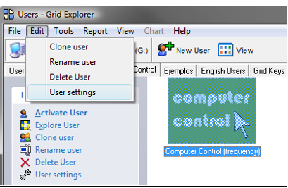
Fig. 6. Grid explorer window.
STEP 3.
A new window will open with a menu on the left side where you should select Input settings → Switch. Enable the option: Enable switch input.
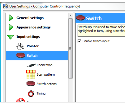
Fig. 7. User settings window.
STEP 4.
Then you should click on Connection (on the left side menu) and select from Switch adapter the Joystick.
STEP 5.
Finally, click OK to finish the configuration process.
If you want to check at any moment if the device is correctly connected and functioning properly you can follow these steps:
STEP 1.
Connect switches to the switch inputs of the USB adapter and connect the USB Adapter BJ-805 (fig. 1) to the PC’s USB port. The USB adapter will be automatically recognized by the PC.
STEP 2.
To verify the connection and the correct functioning of the switches go to: Start Menu → Control Panel → Hardware and sound → Game Controllers, select BJ-805 and click on Properties.
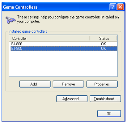
Fig. 8. Game controllers window.
STEP 3.
On the tab “Test” check that when you press the switches circles 1 and 2 lights up corresponding to switch inputs 1 and 2.
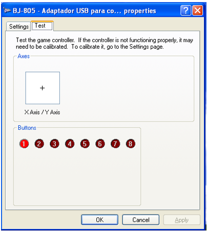
Fig. 9. Verification of switches.
Clean the product with a slightly damp cloth. Always do it with the device unplugged.
If your unit does not work properly, do not manipulate it and get in contact with your distributor.
- Waste electrical products should not be disposed of with household waste!
- Dispose of the waste product via a collection point for electronic scrap or via your specialist dealer. Any unauthorized tampering with, or modifications to the product will annul this warranty.
Within the statutory warranty period we undertake to rectify free of charge by repair or replacement any product defects arising from material or production faults.
Any unauthorized tampering with, or modifications to the product will annul this warranty.
This product complies with the essential requirements of the Directive 2004/108/EC.
The Declaration of Conformity can be downloaded from the product’s webpage at https://bjliveat.com/index.php?controller=attachment&id_attachment=312
1. How to assign other functions to the BJ-805 switches?
If you want to assign different actions to switches you can do it with the software Switch Driver from Sensory Software. You can download it from Sensory Software website: http://www.sensorysoftware.com
2. Is BJ-805 compatible with GRID3?
Yes, BJ-805 it’s compatible with GRID3.
If, despite of correct handling, faults or malfunctions occur or if the product was damaged, please contact us at the address below:
Qinera
c/ Pacífic 51
08027 Barcelona, Spain
Phone: +34 93 285 04 37
Fax: +34 93 553 56 34
e-Mail: info@qinera.com
web: http://www.qinera.com


